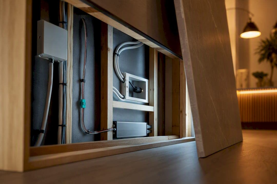
Wire your media wall so the TV stays on a standard 120V receptacle while LED strips and pucks draw power from low-voltage drivers sized to the total LED load, plus 20% headroom, and mounted close to the runs. The one rule that trips up most first-timers: never power a television off an LED driver circuit. Keep the two systems separate from the outlet box forward, and everything downstream gets easier.
TL;DR:
- Use a dedicated outlet for the TV on a standard 120V receptacle and keep LED drivers on a separate low-voltage circuit to prevent interference or safety issues.
- Select LED strips based on voltage and run length; 12V and 24V strips are preferred for longer runs, with 24V reducing current and voltage drop.
- Size your driver wattage at least 20% higher than the total LED load to avoid flickering and premature failure, and verify the circuit's amperage capacity.
- Plan for extra outlets behind the wall to accommodate future upgrades and ensure proper surge and safety protection, including labeling all components.
- Follow specific wiring schematics for different setups, avoid mixing low-voltage and mains wiring, and confirm dimmer compatibility with your driver before installation.
Table of Contents
- What Kind Of Media Wall Lighting Circuits Do You Need?
- How Should You Plan Outlets, Loads, And Circuit Separation?
- What Do Typical Wiring Diagrams Look Like?
- Which Dimmers And Controllers Actually Work With Your Driver?
- What Should You Check Before Closing The Wall?
- Lessons From Building These Walls Every Day
- The Truth About Wiring A Media Wall Yourself
- Skip The Wiring Guesswork With A Kit Built For It
- Sources
- FAQ
What Kind Of Media Wall Lighting Circuits Do You Need?
The circuit you build depends entirely on which LED type you pick, because voltage and wattage dictate driver placement, wire gauge, and how long a run can stretch before it dims at the far end.
5V bias strips run off USB power and are the simplest option for outlining a TV frame. They pull almost no current, but they are picky. Manufacturer guidance for bias lighting warns against feeding a 5V strip from a 12V source, since some dimmer controllers accept a 5 to 24V range without actually converting voltage internally, which can fry a low-voltage strip fast.
12V and 24V strips dominate media wall builds because they tolerate longer runs and higher output. As a general rule, 24V halves the current draw for the same wattage, which means less voltage drop over distance and thinner practical wire runs. If your backlight loop wraps a 75 inch panel and two side returns, 24V is usually the safer bet.
COB and dotless strips give a smoother, dot-free glow that reads more like a light bar than individual diodes. They run hotter per linear foot, so heat sinking (usually an aluminum channel) matters more than with standard strips.
Puck and recessed LEDs work well for alcove shelving or accent lighting inside a slat panel, wired in parallel off a single driver rather than daisy-chained end to end.
RGB and RGBW addressable strips need both a power feed and a separate data line to the controller, which is where a lot of DIY wiring goes wrong.
For sizing, use one formula and stick to it:
- Total strip wattage × 1.2 = minimum driver wattage.
- A long run of 12V strip at 5 watts per foot requires a driver rated for at least 20% more wattage than the total strip wattage to avoid flicker and premature failure.
- Undersizing here is the single most common cause of flicker and premature diode failure, according to Simple Lighting's installation guide.
- Choose an IP20 driver and strip for dry, enclosed cavities; step up to IP65 only if the run sits somewhere humid, like above a bar or near a fireplace insert.
Mount bias strips roughly 2 inches back from the TV edge for even glow, and always start your run from the power end so voltage drop doesn't creep into the far corner. That detail comes straight from MediaLight's own installation instructions, and it applies to nearly any 12V accent strip, not just bias kits.
How Should You Plan Outlets, Loads, And Circuit Separation?
Your TV belongs on a standard 120V duplex receptacle, ideally recessed behind the panel so the cable and plug disappear. Your LED drivers, meanwhile, either plug into their own nearby 120V outlet or tie into a dedicated low-voltage feed run during framing. The two should never share a circuit path in a way that lets one interfere with the other, and a driver should never be pressed into service as a power source for anything mains-rated. This isn't a style preference. It's the core safety principle behind every media wall wiring diagram worth following.
Here's how to actually size the circuit once you know your fixture count:
- Add up the wattage of every LED run, strip, and puck light on the wall.
- Multiply that total by 1.2 to get your required driver capacity, per the headroom rule that keeps drivers from running hot at full load.
- Convert driver wattage to amps (watts ÷ voltage) to confirm you're nowhere close to tripping the breaker feeding that outlet.
- Check that your TV, soundbar, and any streaming boxes are on a separate 15 or 20 amp branch circuit from major household loads, not sharing a circuit with a refrigerator or space heater.
- Add a second outlet if you're running a receiver, gaming console, or subwoofer. Most media walls end up needing more receptacles than people plan for.
Pro Tip: Rough in at least one extra outlet behind the wall even if you don't need it yet. Pulling wire again after drywall and panels go up is a miserable weekend, and future soundbars, smart hubs, or a second driver will thank you.
Surge protection deserves a line item here too. A 1,000-joule surge protector rated for wall-mounted setups is cheap insurance against the voltage spikes that quietly shorten the life of TVs, receivers, and LED drivers alike. If your local code or personal preference calls for AFCI or GFCI protection on that branch circuit, confirm it with an electrician before you close up drywall. It's far easier to add now than to retrofit later.
Label every driver and junction point before you close the wall. A Sharpie note inside a cover plate ("12V driver, backlight loop, 96W") saves the next person, possibly future you, from guessing during a repair.
What Do Typical Wiring Diagrams Look Like?
Three setups cover most media wall builds. Each keeps low-voltage LED wiring physically and electrically separate from the 120V circuit feeding the TV.
Schematic A: Four-sided 12V backlight. A 120V outlet feeds the driver, which sits inside the wall cavity or a service niche behind the panel. From the driver, 18 to 20 gauge two-conductor wire runs to each side of the LED loop, with inline connectors at the corners rather than soldered joints if you want easy future removal. The TV plugs into its own recessed 120V outlet, wired on a separate run back to the panel or at minimum a separate receptacle from the driver's outlet.
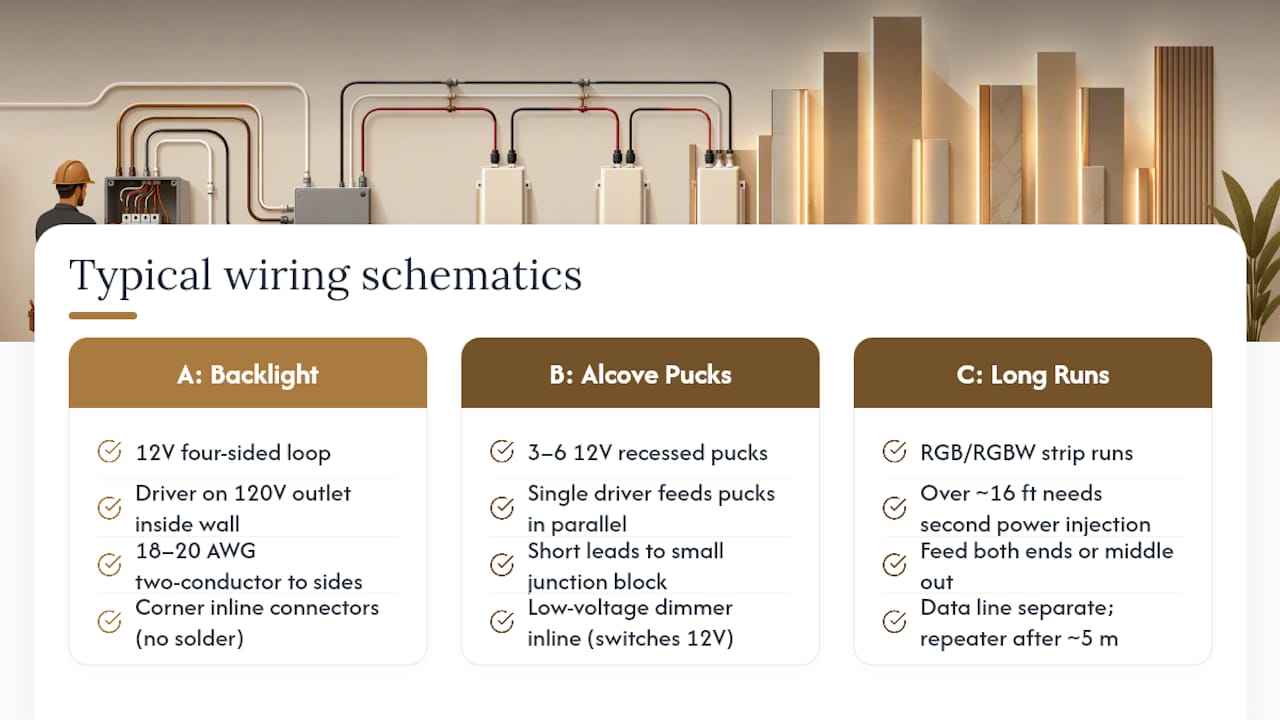
Schematic B: Alcove pucks on a single driver. One 12V driver feeds three to six recessed pucks wired in parallel, each with its own short lead back to a small junction block. A wall-mounted dimmer or switch sits inline on the low-voltage side, not the mains side, so you're switching 12V, not 120V, at the wall plate.
Schematic C: Long RGB/RGBW runs. Anything over roughly 16 feet needs a second power injection point partway down the run, not just one at the start. Feed power in from both ends, or from the middle out, so voltage doesn't sag by the time it reaches the last few feet of strip. The data line for the controller runs separately from the power leads and should use a signal repeater past about 5 meters to prevent color drift or stuttering.
Across all three, keep low-voltage wire at least a few inches from any mains cable where they run parallel, and never bundle them in the same unclamped cable run. Use listed connectors rated for the wire gauge, and avoid twisting bare copper together and hoping electrical tape holds. When cornering LED strips around a panel edge, use a gradual bend or a loose loop instead of a sharp fold. Compressing the copper strip at a tight corner is one of the fastest ways to crack a trace, a tip that comes directly from MediaLight's cornering guidance.
Which Dimmers And Controllers Actually Work With Your Driver?
This is where good wiring diagrams fall apart in practice, because not every dimmer works with every driver, and the mismatches don't always announce themselves right away.
- IR and RF remotes are the simplest option, pairing a small receiver with the driver output. They work well for single-zone strips and pucks but don't scale cleanly across multiple rooms.
- TRIAC (leading-edge) dimmers are designed for resistive loads like old incandescent bulbs, not most LED drivers. Pairing one with a non-dimmable driver is a common cause of buzzing, flicker, or a strip that only half-dims. Confirm your driver is explicitly rated for TRIAC dimming before wiring one in.
- 0 to 10V dimming gives smooth, flicker-free control and is common in higher-end drivers, but it requires a compatible dimmer on the low-voltage side, not a standard wall dimmer swapped in from a lamp circuit.
- PWM (pulse-width modulation) controllers are standard for RGB and RGBW setups and usually come paired with their own app or remote.
- Smart integrations through Matter, Alexa, or Google Home route through a hub or smart plug on the driver's 120V feed, or a smart LED controller on the low-voltage side, depending on the product.
For addressable RGB strips, keep power distribution and data wiring as separate physical runs. A single long data line without a repeater is a frequent culprit behind strips that stutter or show color drift halfway down the wall.
What Should You Check Before Closing The Wall?
Run through this list before drywall, panels, or trim go up for good, because every item here is far cheaper to fix now than after the wall is finished.
- Confirm the TV's outlet is installed and positioned per NEC-informed guidance for wall-mounted TVs, not just wherever seemed convenient during framing.
- Secure every driver to a stud or mounting bracket, don't let it dangle on its own wire, and label each one clearly.
- Use only listed, UL or ETL-rated drivers and connectors, skip the unmarked components in bargain LED kits.
- Power everything on and watch for flicker or dimming at the far end of each run before you close anything up. That's your early warning for a driver that's undersized or a connection that's loose.
- If you're adding outlets, rerouting branch wiring, or you're not fully confident in your load calculations, bring in a licensed electrician. This is not the step to guess your way through.
A lighting plan is not a substitute for proper receptacle placement. Even a beautifully wired LED backlight doesn't meet code requirements for TV power on its own, the dedicated receptacle guidance still applies regardless of how the lighting is wired.
Lessons From Building These Walls Every Day
Pre-cut, pre-labeled panels with built-in wire channels solve the problem most DIYers hit first: not knowing where the driver is supposed to live relative to the LED run. When that path is already routed for you, cornering mistakes and driver placement guesswork mostly disappear. The most common fixes we walk customers through involve moving a driver closer to the run and reworking a connector that was never rated for the load in the first place.
The Truth About Wiring A Media Wall Yourself
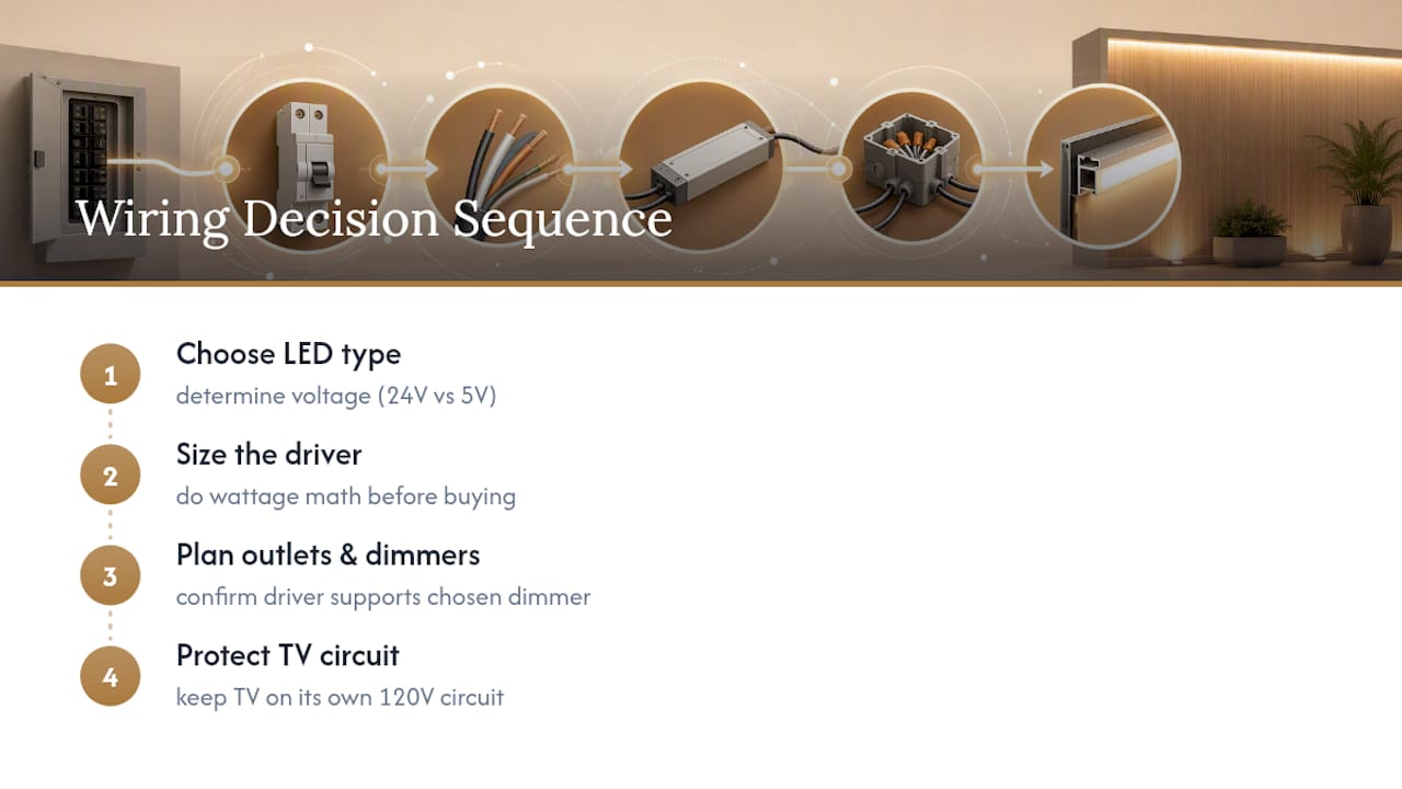
Most guides make LED wiring sound harder than the electrical work behind it actually is. The real skill isn't running wire, it's sequencing decisions correctly: pick your LED type first, size the driver second, and only then plan outlet placement and dimmer compatibility. Do it backward, buying a dimmer before confirming the driver supports it, say, and you'll be troubleshooting flicker for a weekend that should have taken an afternoon.
Where conventional advice falls short is treating all LED wiring as one generic category. A 24V COB run and a 5V USB bias strip have almost nothing in common electrically, yet plenty of tutorials lump them together with one blanket set of instructions. That's how people end up feeding a 5V strip from a 12V source and wondering why it died in a week.
If you take one thing from this guide, prioritize driver sizing before anything else. Get the wattage math right, keep the TV on its own 120V circuit, and the rest, dimmers, controllers, even cosmetic wire routing, falls into place with far less trial and error.
— Jake
Skip The Wiring Guesswork With A Kit Built For It
Themediawallstore is the alternative to figuring out driver placement and wire routing from scratch: our Media Wall Kits ship with pre-cut, pre-labeled panels and hidden wire channels already routed for standard driver locations, so you're following a labeled path instead of reverse-engineering one.

If you already have a wall built and just need the lighting piece, browse LED and ambient lighting accessories for drivers, diffusers, and bundles sized for common run lengths. Want a second opinion on layout before you commit to a design? The Full Design & Quote package runs $299 one-off and gets you a plan built around your actual wall dimensions, not a generic template. Bay Area homeowners who'd rather hand off the whole install can also ask about White-Glove Installation once a design is locked in. Start by looking through the shop to see which kit matches your space.
Sources
For deeper specs, check MediaLight's installation instructions, Simple Lighting's driver-sizing guide, and Themediawallstore's NEC-based outlet guidance. For color temperature choices on accent lighting, Divine Prints' lighting guide covers CRI and the 30 degree rule.
- MediaLight Mk2 v2 installation instructions — MediaLight Bias Lighting
- LED strip lights for media walls: complete guide — Simple Lighting
FAQ
What lights should you use in a media wall?
Most builds use 12V or 24V LED strips for backlighting, COB strips for a smoother glow, and recessed pucks for alcove shelving. The right choice depends on run length and how much heat the space can dissipate, and Themediawallstore's lighting accessories cover drivers and diffusers sized for typical wall dimensions.
How many LED lights can you run off one driver?
It depends on wattage, not a fixed count. Add up the total wattage of every strip or puck on that driver, multiply by 1.2 for headroom, and match that number to the driver's rated capacity rather than guessing by fixture count.
Can you run a TV off a lighting circuit?
No. A TV should stay on a standard 120V receptacle, never off a low-voltage LED driver, according to electrical safety guidance for LED installations. Mixing the two risks both the driver and the TV's power supply.
How do you show LED wiring in a circuit diagram?
LED runs are typically drawn as a power source (the 120V outlet) feeding a driver, then low-voltage lines from the driver to each strip or puck, labeled with gauge and voltage. Mains and low-voltage lines should be shown and wired as physically separate paths, never merged on the same schematic run.
Do you need a dedicated circuit for media wall lighting?
Not always. Most LED driver loads are small enough to share a standard household circuit, but the TV and any high-draw AV gear should have their own outlet, ideally on a separate branch from major appliances. When in doubt on load calculations, get an electrician's assessment before finishing the wall.